条件に該当する製品2376件
-

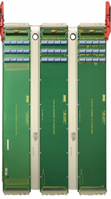
2-Slot, 6U/3U VPX Development SystemType 39 E-Frame
ELMA バックプレーン OpenVPX 試験 環境Features
- 2-slot test & development platform for 3U and 6U VPX and OpenVPX™ boards
- Each slot can be configured independently for power requirements
- 1.6” slot pitch accommodates wider modules compatible with VITA 48.5 (air
flow-through), and provides easy access to components on either side of boards - More than two modules may be interconnected with additional 2-slot backlanes
- Enables use of standard VPX RTM modules and access to J1 high speed signals
- Chassis power input: 90-264 VAC autoranging, total power 700 watts
- High performance cooling fans
- Aluminum construction with scratch-resistant black painted finish
- Built-in Voltage Monitor with green LEDs for bus voltages compliance
- Top handle for ease of portability, desktop feet on bottom
-
Power Interface Board (PIBs)6U, OpenVPX™ Backplanes
ELMA バックプレーン VITA62 防衛 -
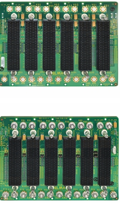
3U 6-Slot OpenVPX BackplaneBKP3-CEN06-15.2.2X-3
ELMA バックプレーン OpenVPX 防衛Description
Designed to meet VITA 65, the 6-slot OpenVPX features a data plane
with 1 Fat Pipe on each slot routed to the switch slot in slot 6. The conrol
plane features an Ultra Thin Pipe on each slot routed to the switch slot.
This backplane does not have an expansion plane.
Features
• Compliant to the VITA 65 Standard.
• Uses the rugged 3U-160 Eurocard form factor
• High-speed EPT Velox connector
• Provides built in ESD ground protection in every slot -
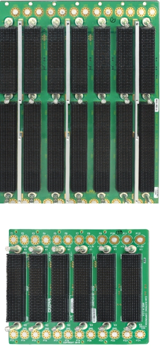
VPX Power and GroundBACKPLANES
ELMA バックプレーン VPX 防衛DESCRIPTION
Elma’s VPX power and ground development backplanes
are simple and cost-effective development tools to develop
a VPX based system. All of the pins are user-defined.
Power for 3.3V, 5V and 12V are included. The rear
connectors are all fully loaded. For use with Elma’s slot to
slot or slot to I/O bulkhead cable products during system
development.
Features
■
■ Compliant to the latest VITA 46 / 65 specifications
■
■ Power and ground only backplane for simple and low
cost development
■
■ 3.3V, 5V, and 12V power
■
■ P0-P6 pins are user-defined
■
■ NVMRO, SYSRESET#, SYSCON# and maskable reset
are supported -
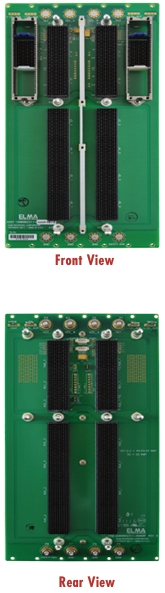
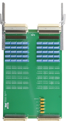
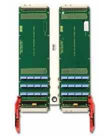
VPX Test Backplane
ELMA TOOL/開発環境 VMEbus 試験 環境Description
The Elma Bustronic 6U VPX 2-slot test backplanes are unique tools
that enable developers and system integrators to test VPX boards. The
backplane allows the user to power up test their J1 fabric connections
as they would be interconnected in the target application. Signals can
be passed from one slot to the next via high speed interconnecting
cables.
Additional 2-slot Test Backplanes can be used in a larger chassis to
interconnect the J1 primary fabric in any serial topology desired.
Signals in any other connector position may be interconnected or
accessed using optional MultiGig cable headers or typical commercial
RTM modules. Note that rear cables and RTM connectors cannot be
used at the same time in the same slot.
ELMA
Backplanes
Unlike other access methods, such as rear VPX cables alone or
special high speed RTM break out boards, the Elma Bustronic 2-slot
test backplane allows primary J1 fabric signals to be accessed/
interconnected/injected without interfering with the use of an existing
RTM module designed for J2-J6 IO connector signals. Custom
backplanes are often required to interconnect the primary fabric
signals between multiple VPX blades for a specific application.
However, it is desirable to be able to connect two or more such blades
with a test backplane before investing the time or expense of a custom
VPX backplane.
Features
• For convenient testing of VPX/OpenVPX boards
• Designed to meet the latest VITA 46.0 and VITA 65 specifications
• Accepts either 3U or 6U VPX cards by use of the configuration
jumpers on the rear of the backplane and a 3U shelf divider
Rear View
Related Products and Applications
Highly integrated applications such as:
• Open frame test chassis - need a chassis for your backplane?
• Wider slot pitch allows more space for attaching to probes
• Allows simultaneous access of J1 fabric signals with standard VPX
RTM module for J2-J6 signals
• More than two VPX modules may be interconnected by using
additional 2-slot test backplanes -
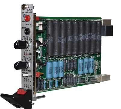
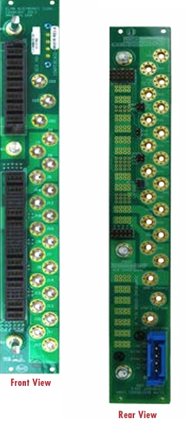
3U VPXLOAD BOARD
ELMA TOOL/開発環境 VMEbus 試験 環境DESCRIPTION
The Elma VPX load board is designed to be compliant with ANSI/VITA
mechanical and electrical connection standards. Developed to enhance
testing of VPX systems, the load board aids the system designer in assuring
adequate chassis cooling and verifying that the VPX chassis is capable of
meeting the power requirements of the system (or VITA specs). The load
board functions to test a system’s cooling capabilities by first applying the
load to the power supply for verification and creating the necessary heat
to confirm chassis cooling. By locating hot spots in the chassis,a system
designer can verify where to optimally redirect the airflow to prevent over
heating. The load board increases productivity by quickly and accurately
characterizing systems at low cost.
The 3U VPX load card features a microcontroller-based stepped load
control. Therotary switch selects the voltage setting while pushing the ON
switch will cycle between different power levels shown on the LED display.
The set load power levels are saved in EEPROM. The design is RoHS
compliant and has an operatingtemperature range of 0 degrees C to 70
degrees C.
Features
■
■ Load board for VPX systems, meets ANSI/VITA 46 mechani
cal and electrical connection standards
■
■ Convection and conduction-cooled versions available
■
■ Verifies chassis can meet power requirement and specifica
tions for VPX
■
■ Assists in locating hot spots in the chassis
■ Go/No-Go indicators for 12V, 3.3V, 5V, +12V_Aux, -12V_Aux & 3.3V_Aux.
■
■ Two test point outputs and microcontroller- based rotary
switch selector for voltage settings, markings for SIG and
GND
■
■
■ Power reset button (to minimum level), SYSRESET signal on
the two test point outputs
■
■ Power level LED (1, 2, and 3) and push button (Step UP)
indications
■
■ RoHS compliant
■
■ 6U versions are also available -
VME Test ExtenderANSI/ VITA 1-1994 compliant
ELMA EXTENDER VMEbus 試験 環境Description
All models of our VMEbus high performance J1, or J2, or J3 extender boards extend
all 96 signals, including power and ground per the ANSI/VITA 1-1994 specifica
tion.
The VME extender boards are designed to bring a circuit card completely out of a
card cage or enclosure so that it can be tested or debugged. This provides access
to both sides of the test board. There are test points for all of the lines on each
96-pin connector. Each signal, power, and ground line can be individually isolated
with the DIP switches. The VME extender board accommodates use in 3U x 220mm
to 12U x 400mm chassis.
The extenders utilize an 8-layer stripline design, providing balanced and optimal
impedance. Elma’s test extenders are designed to maximize performance, minimize
noise and give the customer the most reliable, cost-effective products possible.
The rugged card guide handles securely hold the test board, ensuring a reliable
connection.
ELMA
Backplanes
Features
• Designed to meet mechanical and electrical connection requirements of ANSI/
VITA 1-1994 and IEEE P1014 specifications
• Assembled from 3U segments - VME J1, VME J2, or 96-pin universal modules
plane
• Test points for all of the lines on each 96-pin connector
• All J1, J2, and J3 connector pins can be individually switch isolated
• Designed for use in 160mm, 220mm, 340mm, 400mm chassis
• Rugged inject/eject card guide handles -
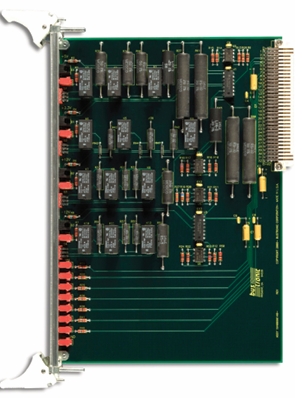
VME/VME64x Load BoardsVITA Backplanes
ELMA バックプレーン VMEbus 試験 環境Description
The Elma Bustronic VME/VME64x load board enhance provides a means to test the
power generated and cooling capability of VME systems.
The 6U VME/VME64x load board saves significant time and expense by confirming
a system’s operating specifications. The load board functions to test a system’s
cooling capabilities by applying a load to the power supply for verification, then
generating necessary heat to confirm the chassis’ cooling. This enables locating hot
spots in the chassis so the airflow can be properly directed.
Features- Conforms to electrical and mechanical connections of ANSI/VITA 1, 1994 for
VME and ANSI/VITA 1.1, 1997 for VME64 extensions
ELMA
• Verifies chassis can meet power requirement and specifications for VME/VME64x - Aids in locating hot spots in the chassis
Backplanes
• Go/No Go LED indicators for +5V, +3.3V, +12V, -12V (within ± 5%) - Primary test points +V1, +V2, -V1, -V2, ACFAIL, SYSRESET,
SYSFAIL, and GROUND - Power supply loading varies with front panel switches from 0 to 7 amps for
thermal characterization
- Conforms to electrical and mechanical connections of ANSI/VITA 1, 1994 for
-
VME64x Test ExtenderANSI/ VITA 1.1 D2.1 compliant
ELMA EXTENDER VMEbus 試験 環境Description
Elma Electronic VME64x test extenders have been designed to comply with the
mechanical and signal connection requirements of the ANSI/VITA 1.1 – 1997
VME extensions standard.
The VME64x extender boards are designed to bring a circuit card completely out
of a card cage or enclosure so that it can be tested or debugged. This provides ac
cess to both sides of the test board. There are test points for all of the lines on each
160-pin connector. Each signal, power line can be individually isolated with the
DIP switches, but they are tied to power and ground planes. The VME64x extender
board accommodates use in 160mm and 220mm chassis.
Additional features include high and low frequency decoupling capacitors, five
signal layers and seven power and ground planes. Elma Electronic test extenders
are designed to maximize performance, minimize noise and give the customer
the most reliable, costeffective products possible. The rugged card guide handles
securely hold the test board, ensuring a reliable connection.
ELMA
Backplanes
Features
• Designed to meet mechanical and electrical connection requirements of ANSI/
VITA 1.1 D2.1 VME extensions standard
• All J1 and J2 connector pins can be individually switch isolated, but are tied to
power and ground planes
• Test points for all 160 pins of J1 and J2
• Superior power distribution utilizing 2 oz. copper power and ground planes
• Optional J0 connector available
• Designed for use in 160mm and 220mm chassis
• Rugged card guide handles most legacy VME products -
220MM, 400MM VME TEST EXTENDER
ELMA EXTENDER VMEbus 試験 環境FEATURES
• Designed to meet mechanical and electrical connection
requirements of ANSI/VITA 1-1994 and IEEE P1014
specifications
• Assembled from 3U segments - VME J1, VME J2, or
96-pin universal modules plane
• Test points for all of the lines on each 96-pin connector
• All J1, J2, and J3 connector pins can be individually
switch isolated
• Designed for use in 160mm, 220mm, 340mm, 400mm
chassis
• Rugged inject/eject card guide handles